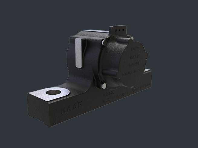
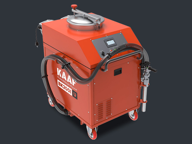
Sanding System
In railway operations, maintaining optimal wheel-rail adhesion is critical for both safety and performance. Sanding systems play a key role in improving traction, braking efficiency, and overall operational reliability, particularly in challenging rail conditions such as wet, icy, or contaminated tracks. A sanding system enhances the friction coefficient between the wheel and the rail by delivering a controlled amount of sand to the contact surface. This process effectively prevents wheel slip during acceleration and wheel slide during braking, ensuring smooth and safe operation of rolling stock.”

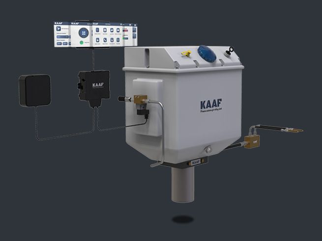
Sanding operation starts after the receiving blowcommand from the vehicle. There are two ways of sanding command; automatic command from the WSP system or manually pushing button command from the vehicle control panel. After receiving the sanding command, KKS-100 starts running with both compressor and solenoid.
At the routingunit, the pressured air exiting from the compressor come across with sand which flows from the sanding tank by the way of batching unit. The pressured air and sand mixture exits from the blasting unit pass the sanding hoses. Lastly, the mixture is being blownto rail and wheel intersection by the nozzle.
“EN 61373 SHOCK AND VIBRATION TEST CERTIFICATED. MANUFACTURED ACCORDING TO EN 15085 WELDING MANUFACTURING STANDARD”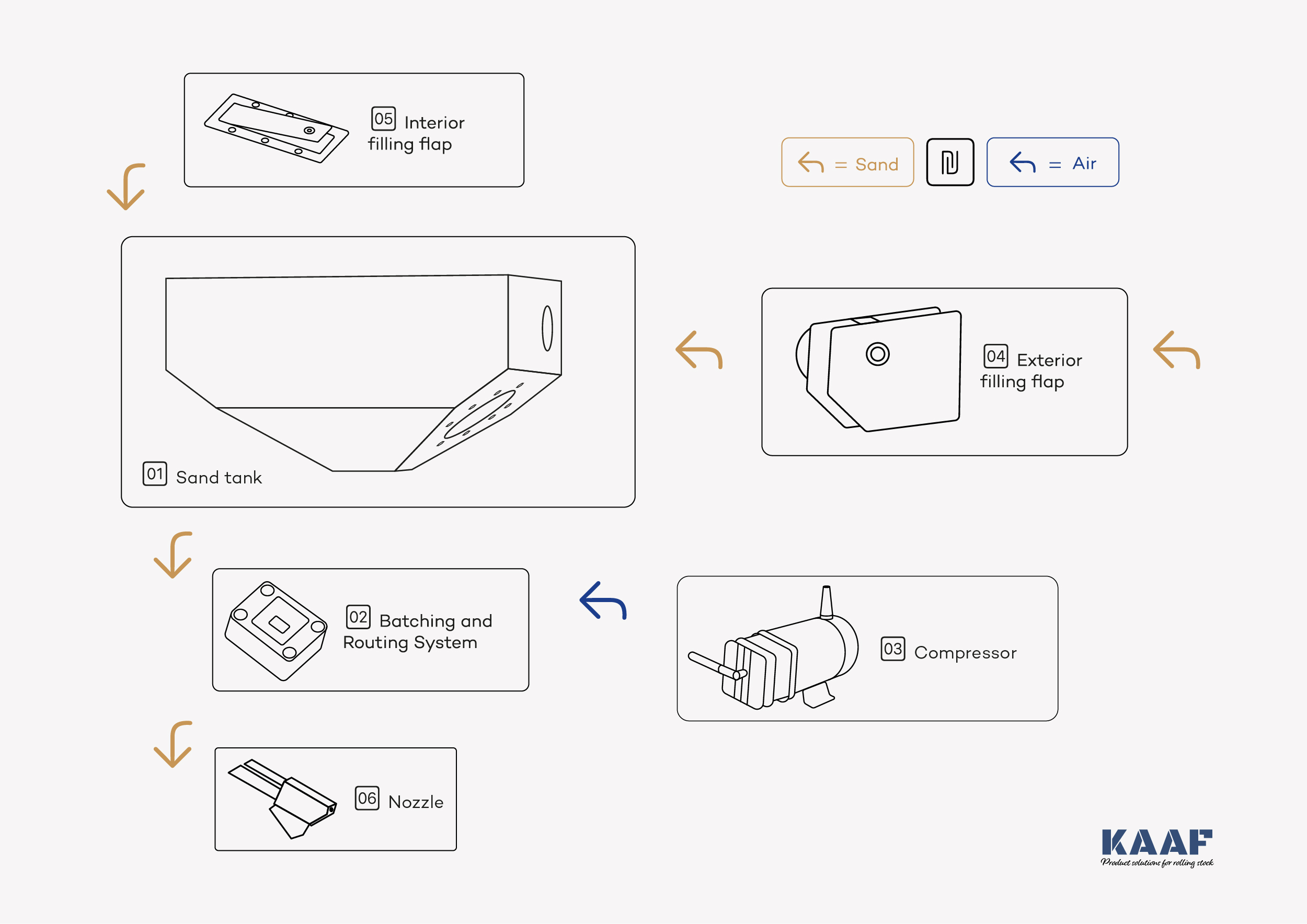

Sand Tank
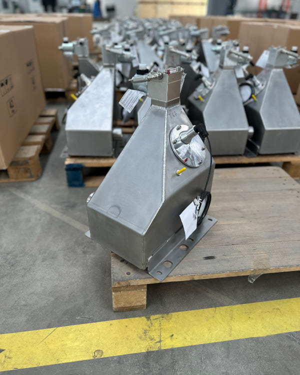
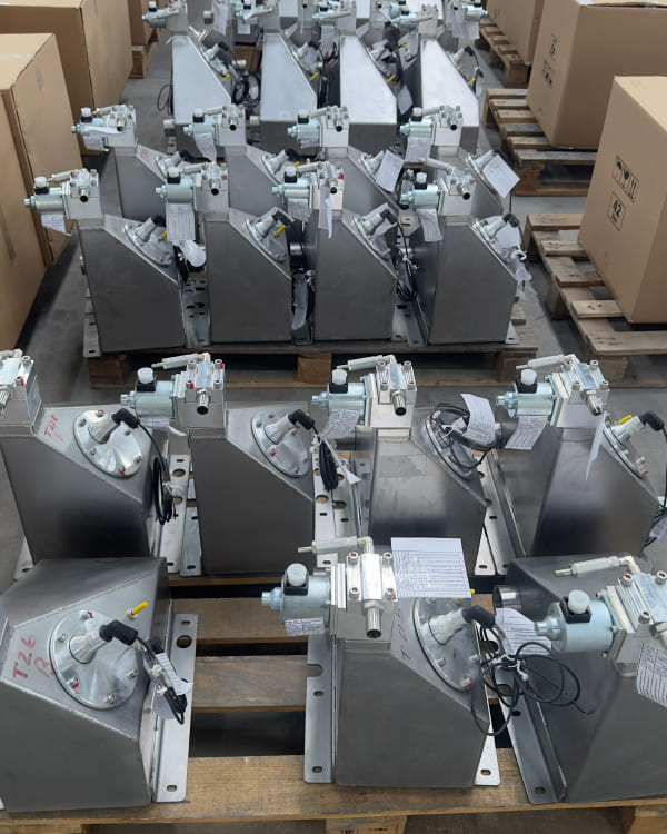
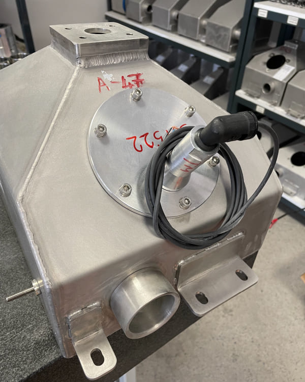
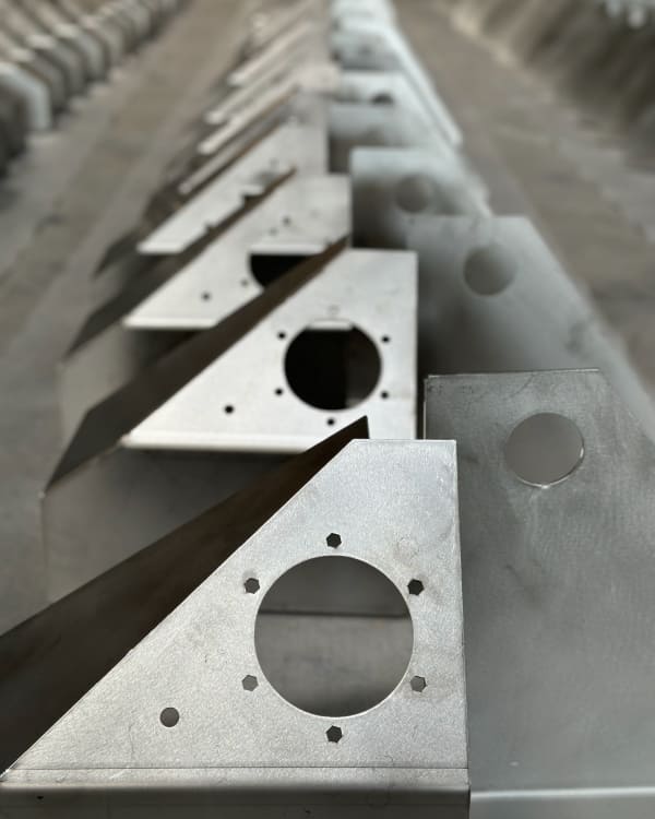
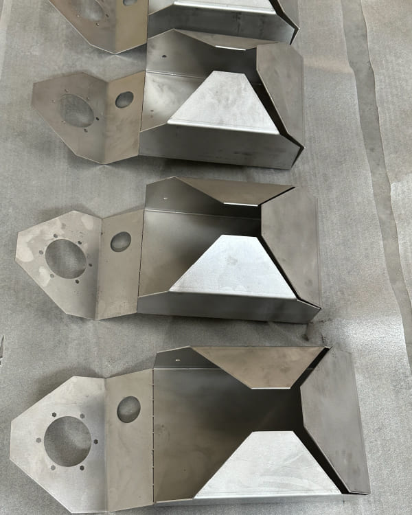
One of the most important issues in sanding systems is the design and production of storage volumes with the correct geometry and sealing level. Sand tanks are uniquely designed for every project according to customers' requirements. Materials are chosen for their high wear resistance against sand-pressured air, such as aluminium alloy or stainless steel. All openings, such as sand filling caps, batching openings, sensor connections, indicator glasses, etc., are insulated against air and moisture. Thus, the sand is prevented from becoming lumpy due to moisture. The tank geometry is designed using various methods, considering system limitations;
| Parametre | Değer |
|---|---|
| Material | A15754/ A16082 / AISI 304 |
| Mounting Place | Under Frame |
| Mounting Type | Screw |
| Tank Volume | Optional (14... 30 liters) |
| Safety Class | IP65 |
| Compatible Filling Types | Top Filling Flap / Lateral Filling Flap / Both |
| Güç | 45W (S3) |
| Earthing Type | Screw Earthing |
Batching and Routing System
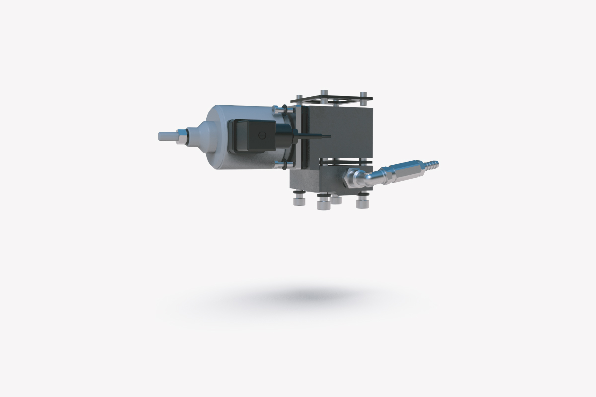
The batching and routing system consists of 3 subcomponents:
1. Batching Unit,
2. Solenoid,
3. Routing Unit,
The batching system, which is directly connected to the sand tank, allows the desired amount of sand to reach the routing unit while the sand is passing through the batching unit. The amount of sand to be blown can be adjusted from 400 to 1200 gr/min by means of the adjustable solenoid. Sand arrives in the routing system after being dispensed from the batching unit. The sand from the batching unit and the compressed air from the compressor are combined and transmitted to the nozzle through the distribution hoses.
| Parametre | Değer |
|---|---|
| Sand Flow | 600-1000 g/30san ± 7% adjustable in range and tolerance |
| Operating pressure | 1bar |
| Batching Method | Batching with solenoid (Electro-mechanical adjustment)+[@Parameter] IP65 |
| Safety Class | IP65 |
| Useable Max Speed | 160km/h |
| Operating voltage | 24V DC (36, 72 and 110V DC options are also available) |
| Power | 45W |
| STANDARDS | |
| Sand Quality and Size | BN 918224 |
| Compressed Air Quality | ISO 8573 Particle class: 7, Density <= 10mg / m, Humidity: 2 |
| Operating temperature | EN 50155 |
| Socket Type | EN 175301-803 |
Compressor
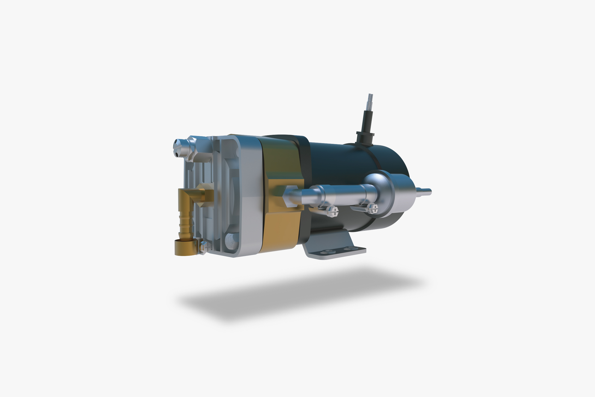
Oil-free compressors offer significant advantages in terms of lifetime and mechanical properties. The required pressurized air is supplied by the oil-free compressor, which has been proven and utilized in numerous railway projects for sanding systems. Thanks to its innovative technology, it provides continuous service with minimal maintenance requirements. The specifications of the compact oil-free compressor are as follows:
| Parametre | Değer |
|---|---|
| Type of fluid | Air |
| Flow | 80 1/min |
| Max. Operating pressure | 1500 mbar |
| Operating pressure | 1000 mbar |
| Motor | DC |
| Nominal Voltage | 24V DC |
| Safety Class | IP56 |
| Power | 250W |
| Weight | 3,8kg |
| STANDARDS | EN 175301-803 |
| Compressed Air Quality | ISO 8573 Particle class: 7, Density <= 10mg / m, Humidity: 2 |

Exterior Filling Flap
Exterior filling flap, located on the vehicle's sidewall, provides the opportunity for quick and practical sand filling during maintenance. The sealing elements placed on the filling flap and in the sand passage pipe prevent any interaction between the environment and the stored sand. Air intake is prevented by a spring-pressed system at the sand filling pipe's mouth. By providing insulation, it eliminates the possibility of sand clumping.
The flap features an open-and-remove system with a square-head, spring-loaded lock, which allows it to be closed without the need for a key after unlocking.
An LED signal lamp, located on the filling flap, lights up when the sand level drops below 35%. The lamp can be easily seen and detected from the outside without the need to access the tank or the driver's panel.
| Parameter | Value |
|---|---|
| Material | A16082 |
| Filling Method | Refilling with pistol |
| Mounting Type | Screw |
| Lock Type | Spring Lock |
| Lock Head | 8mm square head |
| Filling Inlet Protection | Spring forced and Rubber |
| Level Indicator Lamp | Green/Red/White Led lamp |
| Safety Class | IP 66 |

Sanding Nozzle
Sanding via the nozzle increases the amount of sand passing between the wheel and the rail by 70% compared to sanding using only the hose. Nozzles produced with blowing outlet diameters of 19-25mm are the most effective sand transporting method between the wheel and the rail. One of the most important aspects of the system is applying the compressed air-sand mixture between the wheel and rail at the correct angle. The nozzle is positioned at a 15° angle to the intersection of the wheel and rail. Sand with an appropriate flow rate maintains the friction coefficient at the required level by remaining between the rail and the wheel. Special brackets, which are designed for each project, provide both positional stability and easy maintenance. Through the heating system added to the nozzle, uninterrupted service is provided in all climate and environmental conditions. The heater maintains the desired temperature in sections of the nozzle with the heat it emits through the sanding opening.
| Parameter | Value |
|---|---|
| Material | A16082/AISI304 |
| Hose Type and Diameter | Sanding Hose |
| Hose Diameter | 19mm |
| Heater Type | Cartridge resistance |
| Heater Power | 50-100watt |
| Operating voltage | 24V DC (36, 72 and 110V DC options are also available) IP67 |
| Safety Class | IP67 |
| STANDARDS | |
| Hose Fire Protection | EN 45545 |
| Electronic Hardware | EN 50155 |
Adjustable Level Measurement Sensor
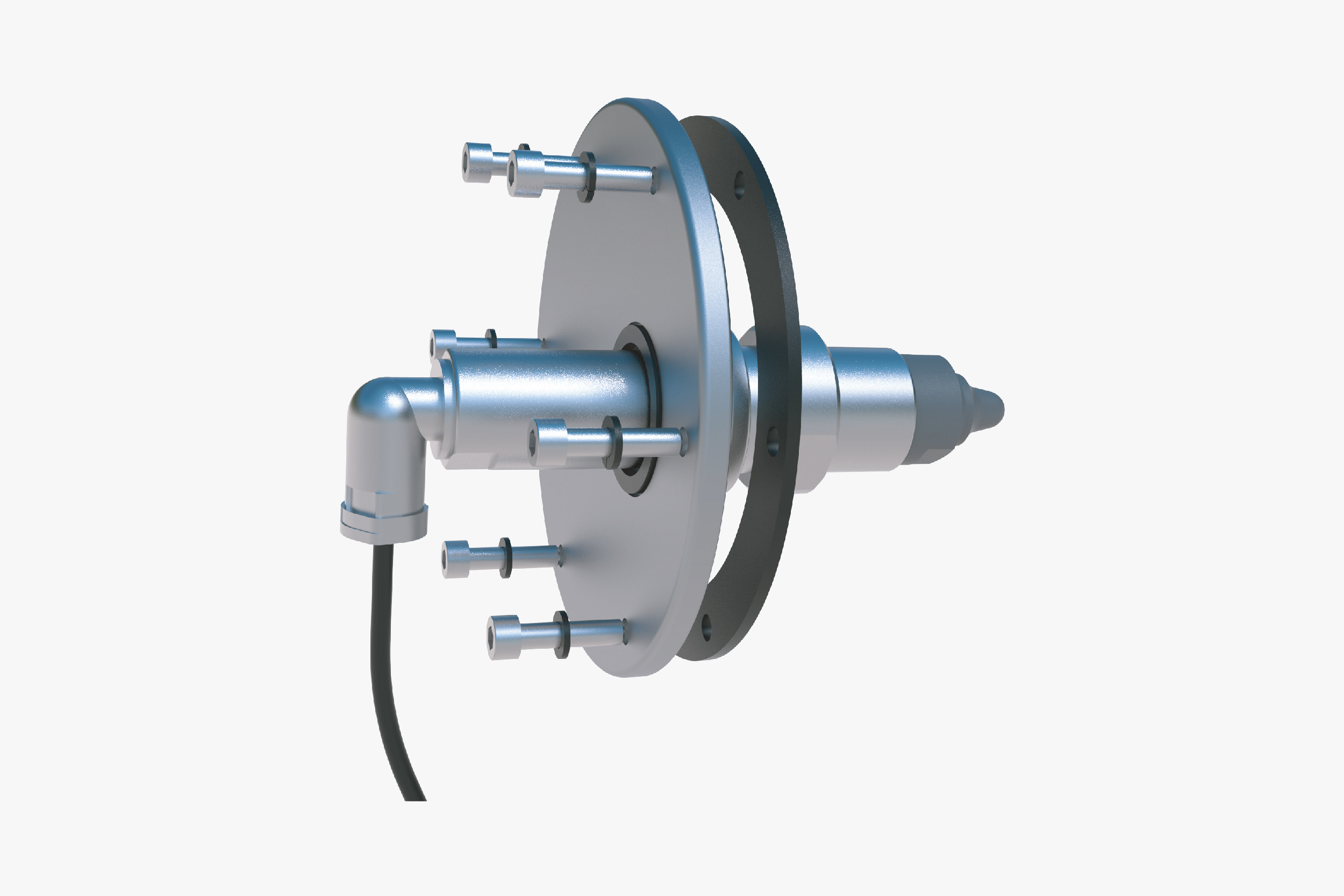
The sanding system has two different digital sand level indicators: one at the exterior filling flap and one in front of the driver. Both indicators receive sand level information from the capacitive level measurement sensor in the tank. The sensor warns if the sand level decreases below the critical level, which is specified according to customer choice. The sensor's changeable positioning option allows for the measurement of sand levels from various heights.
| Parameter | Value |
|---|---|
| Sensor Type | Capacitive level sensor |
| Operating Voltage Range/td> | 10V... 30V DC (36, 72 and 110V DC options are also available) |
| Standard | IEC 60947-5-2 |
| Safety Class | IP67 |
| Operating Temperature Range | -25... 85°C |
| Sensor Dimensions | Ø 30 x 65.5 mm |
| Sensor Housing Material | A15754 / A16082 |
| Positioning | 3 different positioning |
