 TR
TR
 EN
EN
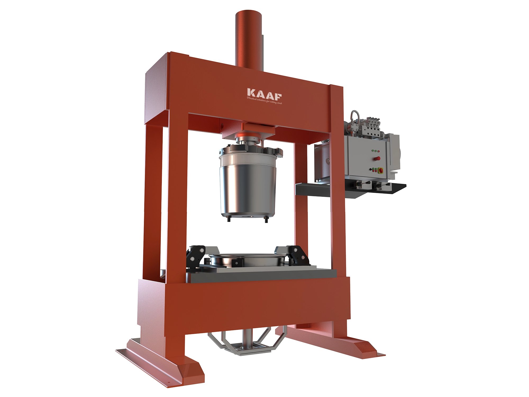
Zemin Altı Tekerlek Presi
Zemin Altı Tekerlek Presi


Zemin Altı Tekerlek Presi Nedir ?
Ön gerilmeli kauçukların, esnek tekerleklerde iç çember ile dış çember arasında montajı ve demontajı yalnızca bu iş için özel olarak tasarlanmış makinelerle mümkündür.
KAAF Esnek Tekerlek Presleri, Bo'54 tipi tekerleklerde gerekli ön gerilme kuvvetini doğru konum, kuvvet ve hızda uygulayarak montaj işlemini güvenli ve hassas bir şekilde gerçekleştirir.
Makine, farklı tekerlek tipleri ve müşteri taleplerine göre özelleştirilebilir yapıdadır. Presleme işlemleri, 500 tona kadar kuvvet uygulama kapasitesine sahip olarak gerçekleştirilebilir. Ayrıca, tekerlek montajı için gerekli kalıp ve yardımcı ekipmanlar da makineyle birlikte özel olarak tasarlanmakta ve teslim edilmektedir.
Zemin Altı Tekerlek Presinin Temel Avantajları
- Atölye zeminine entegre olacak şekilde tasarlanmış yerleşik altyapı, alandan tasarruf sağlayan bir kurulum sunar.
- Kapalı çekme-basınç yapısı, uygulanan pres kuvvetini makine içinde tutar; zemine yalnızca kendi ağırlığını iletir, ek yük bindirmez.
- Opsiyonel yük hücresi (load cell) takibi ile hassas kuvvet uygulama imkânı sağlar.
- Gömülü kurulum, çalışma alanında minimum engel oluşturur; ancak ilk kurulum ve bakım süreci daha karmaşık olabilir.
- Tekerlek presleme işlemi aks takımı ile birlikte yapılabilir.
| Ürün Özelliği | Detay |
|---|---|
| Model | K10438 |
| Makine Tipi | Zemin Altı |
| Montaj Yöntemi | Sıkı geçme konisi ile ön gerilmeli montaj |
| Uyumlu Esnek Tekerlek Tipi | Bochum 54 |
| Uyumlu Tekerlek Çap Aralığı | Müşteri tekerlek çapına göre yönlendirilmiş |
| Makine Boyutları (YxGxD) | Yaklaşık 1200(h) × 2200 × 1200 mm |
| Zemin Altı Yerleşim Boyutları | Yaklaşık 2000(h) × 2200 × 1700 mm |
| Piston Sayısı | Tek piston |
| Makine Gücü | 17 kW |
| Çalışma Voltajı | 380V AC (trifaze) / 50–60 Hz |
| Çalışma Basıncı | 350 bar |
| İşletme Basıncı | 280 bar |
| Test Basıncı | 380 bar |
| Kurs Uzunluğu | 900 mm |
| Maksimum Yükleme Kapasitesi | 0 – 150 ton |
| Açılma Hızı | 0 – 590 mm/dk |
| Kapanma Hızı | 0 – 780 mm/dk |
| Uygun Kauçuk Yağlayıcı | Yumuşak sabun veya uygun başka bir kaydırıcı (opsiyonel) |
| Piston Üst Kalıp Tipi | Uyumlu tekerlek tipine göre değiştirilebilir kalıp |
| Plaka Kalıp Tipi | Uyumlu tekerlek tipine göre değiştirilebilir kalıp |
| Ana Gövde İmalat Yöntemi | Kaynaklı imalat ve sökülebilir bağlantılar |
| Makine Sabitleme Yöntemi | Zemine cıvatalı bağlantı |
| Sıkıştırma Plakası | Hassas işlenmiş, yüksek mukavemetli çelik |
| Tekerlek Lastiği Merkezleme Sistemi | Merkezleme aparatı |
| Değiştirilebilir Montaj Plakaları | Hassas işlenmiş, yüksek mukavemetli çelik |
| Tekerlek Lastiği Tutucu Kol | Kendinden kilitlemeli, takviyeli çelik yapı |
| Sıkıştırma Konisi | Hassas işlenmiş, yüksek mukavemetli ve ısıl işlem görmüş çelik |
| Konik Bağlantı Yöntemi | Tekerlek merkezine cıvatalı bağlantı |
| Toplam Makine Ağırlığı | Yaklaşık 6200 kg (zemin bağlantı donanımı hariç) |
| Hidrolik Bağlantılar | Çelik ve kauçuk hortumlar ile güvenli bağlantı |
| Hidrolik Ünitenin Konumu | Zemin tipi yerleşim |
| Güvenlik | Hidrolik sistem arızalarına karşı mekanik güvenlik önlemleri |
| Yük Bekletme Fonksiyonu (Standby) | Mevcut |
| Yük Sabitleme Fonksiyonu (Hold) | Mevcut |
| Enerji Kaynağı | 380V AC 3 Faz |
| Makine Kontrol Yöntemi | PLC kontrollü sistem |
| Hareket Kontrol Yöntemi | Kumanda kolu ve buton ile kontrol |
| Sistem İzleme Arayüzü | HMI ekran |
KAAF Zemin Altı Esnek Tekerlek Presi Yardımcı Ekipman Listesi
 Sıkıştırma Konisi
 Tekerlek Lastiği Tutucu Kol
 BO'54 Montaj Çivi Tutucu Kalıbı
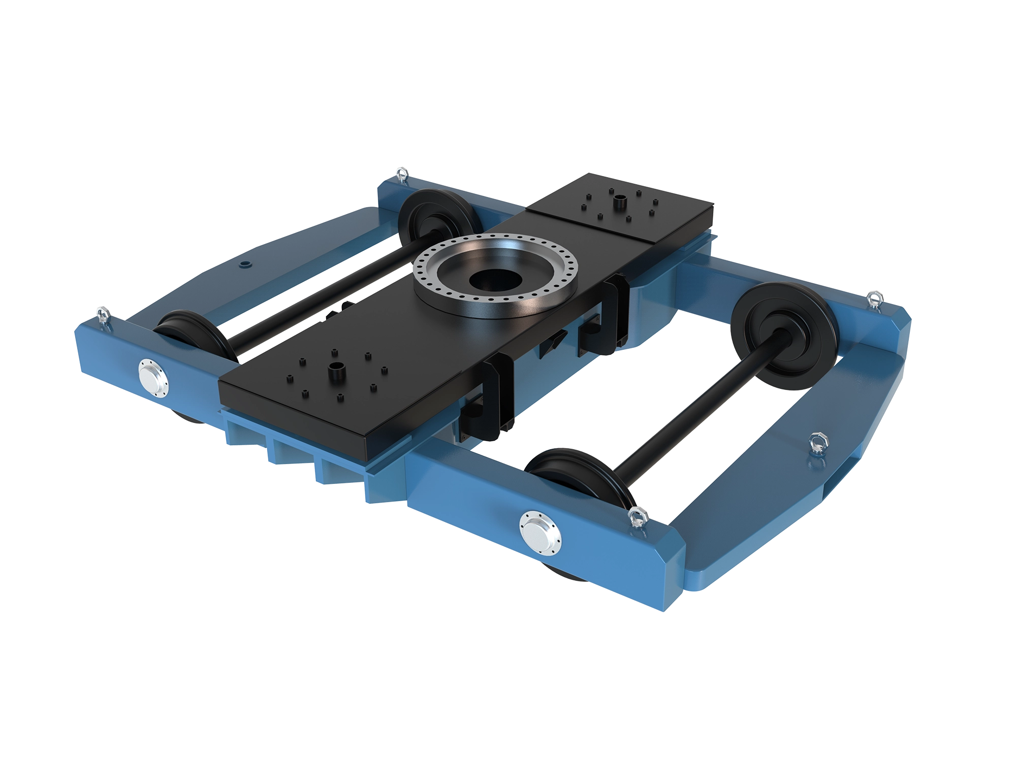
 Tekerlek Merkezi Kaldırma Aparatı
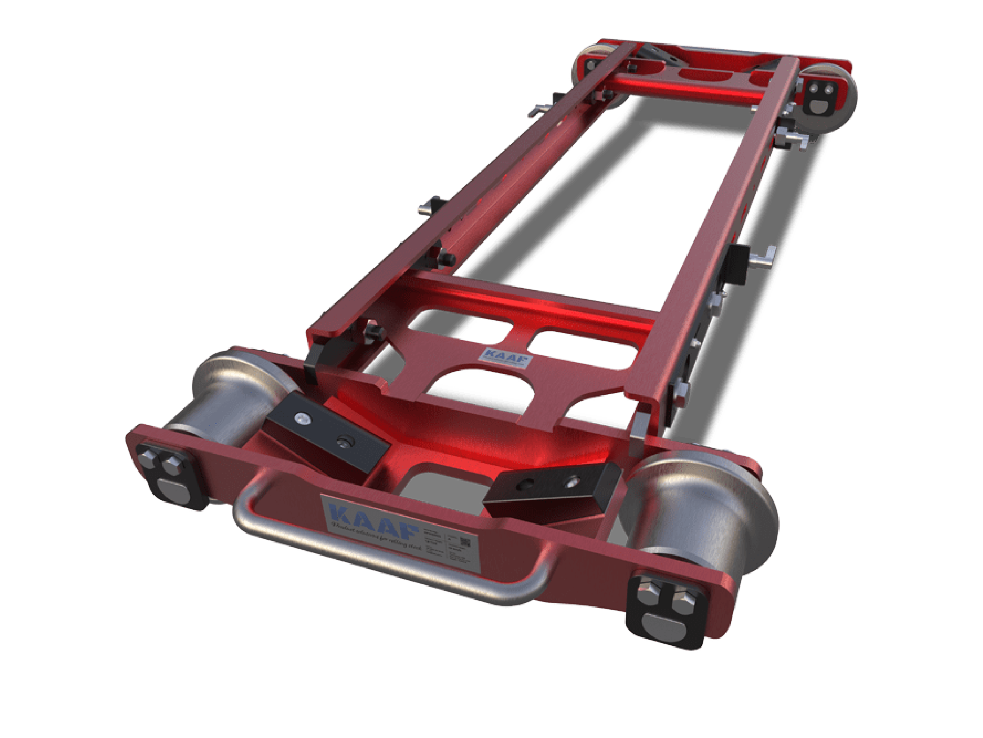
 Montajlı Tekerlek / Lastik Kaldırma Aparatı
 Mobil Montaj Sonrası İşlem Masası
 Anahtar Takımı / Kalite Kontrol Mastar Seti
 Kauçuk Konumlandırma Mastarı
 Bakır Kaplamalı Kauçuk İşaretleme Mastarı
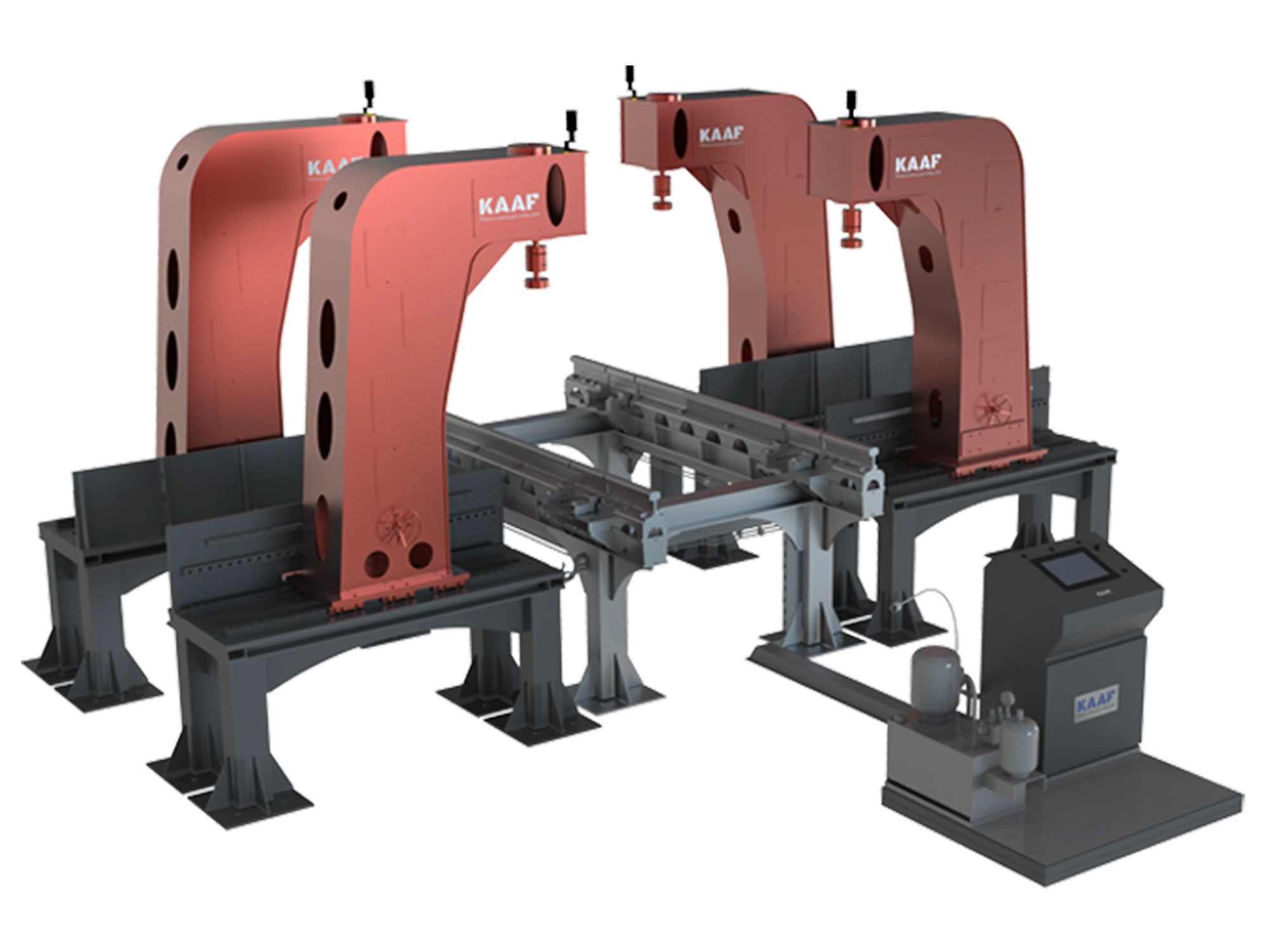
 Pergel Vinç